Reducing the Current Usage of a Battery Powered Pressure Gauge
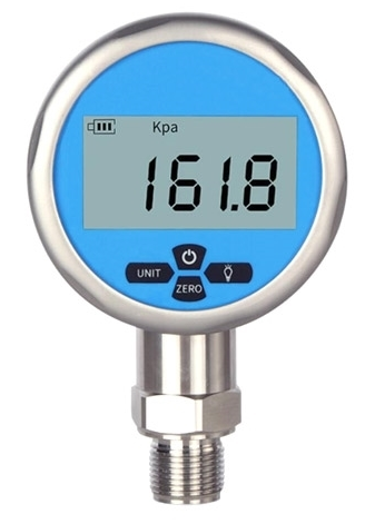
1/18/2025A relative reached out to get my help in designing and assembling a pressure gauge. The main requirements were that it should be portable, have a digital display, be visible outside, and have a button to zero the measurement. Also, the display should be separate from the sensor with a wire so they could position the two independently. Admittedly there were some products that matched this description, but none that had a good enough accuracy and were affordable. In effect they wanted something like this, but with the display separate from the sensor:
I hadn't yet made a device for someone else, so I readily agreed.
The Design
The design was as straight-forward as the request: a microcontroller, pressure sensor, screen and the glue in between. Given that this was the first time I was designing a device powered by a CR3032 I paid special attention to that part of the design. Specifically, it was immediately clear that current consumption should be kept low to limit battery usage. The issue was that the prototype would initially draw 15mA, about 5 times the maximum of 3mA in the battery's specification, so a mix of tradeoffs and technical reading was necessary to reduce the usage that far.
note: What is this used for? It's for monitoring the pressure from an air brush.
The Tradeoffs
The first and most obvious method to lower current usage is by weakening all of the pullup resistors. The pullup values were raised from 5kΩ to 100kΩ, and the frequency of the i2c clock was lowered to compensate for the increased rise time. Both resistance and clock were adjusted until the display reached a refresh rate that was still responsive enough to provide realtime feedback on the pressure reading. I did not record how much this reduced the current usage, but I remember it being significant.
However, a tradeoff being made by choosing weaker pullups. The line is more prone to noise, which is exacerbated by the i2c devices going off-board. This was not a significant issue for this device because the display's refresh rate was in the 10s of hertz, and losing a frame or two would be unnoticeable. In the case of a transmission error, it would try to write an error code to the display, and otherwise continue through the program.
One issue that I had read about regarding i2c but had not encountered yet was that the data line could get stuck in a low state. I ran into this problem here, though, because after some transmission issues the microcontroller had a chance of holding the line low. I knew it was the microcontroller because the registers for the i2c peripheral would show that line was intentionally pulled low. To fix this, the i2c peripheral had to be restarted after a transmission error, which necessitated the following code:
This is apparently a common issue and a common solution. Alternatively, I could have attempted to include some sort of timeout mechanism, but I saw no reason to in this case. The line was not getting stuck that often.
Returning to current usage, the OLED display had to have its contrast lowered, which was simple enough because the OLED was being driven by an SSD1306 which had that functionality built into it. It was lowered to the point it could still be comfortably read outdoors, at which point it drew 1.8mA.
The processor that I had chosen was the STM32L422KBT6, and ST have helpfully published an application note on how much memory settings impact the current consumption for this and related microcontrollers. The most interesting setting was related to the prefetch setting, which is more relevant to the L4 architecture than the others covered in the note. To quote, Neither the prefetch or caches have any influence on the execution speed when the flash memory is available with zero latency. But the impact on the power consumption may be significant. The reason is because if the processor is being run at a slow enough clock (<=16MHz), there doesn't need to be an artificial delay when reading instructions from the NonVolatile Memory. The delay is there because the NVM cannot keep up when the clock is higher than 16MHz. Because of this, prefetch is provided to help by having the NVM ready the next instruction ahead of time. However, prefetch is not necessary when there is no delay because either way it would take one clock cycle to read from NVM. It can be disabled because at that point it's just another source of current draw. Specifically they measured 5.65 mA under their load with prefetch disabled, which went up to 5.9mA when it was enabled.
note: However, this along with other memory related settings are configured for low power consumption when the chip is clocked to less than 16MHz. If you clock it to 2MHz, the low power regulator is used in place of the regular regulator for powering Vcore and the related clocks. This is of course the best way of reducing consumption for any processor, so you don't even need to be aware of the details outside of setting the clock low and enabling low power mode at the start of the program with HAL_PWREx_EnableLowPowerRunMode().
How was I measuring the current consumption?
It's not the most correct method, but I wrote a python script to send measurement requests to my Tektronix DMM 4040 and stored the results in Prometheus, which I graphed. The current measurement was made inline with the positive input voltage. The takeaway is that I did not have sufficient granularity to measure whatever transient power consumption there may have been, but because the measurements did not fluctuate much, I did not need that much accuracy to judge the average current usage. The main goal of this metric was to ensure the battery could power the device. The device is only intended to be powered on for short amounts of time so the effects of drawing excessive current should be less pronounced. In short, I just used a multimeter, but it was enough to see the average current usage go down.
Mistakes
In designing the device, I made the mistake of leaving V+ floating when the device is turned off instead of tying it to ground. This caused confusing behavior where if the power was cycled the chip did not brown out before the screen powered off, causing the chip to enter a faulty state. A few cut traces and a bodge job fixed that issue.
After about two weeks of usage, the wire in between the screen and the main board actually disconnected and had to be re-soldered. After that, a dab of high-strength hot glue (that very much looked like how components are reinforced with epoxy in mass produced products) stopped them from coming apart again.
For better current usage, replacing the OLED with a standard LCD would give enormous saving and potentially offer better contrast in the daylight. I did not end up needing to draw icons or position text accurately, so an OLED offered no benefit. If I wanted both, I could use an e-ink display, but that is both expensive currently and doesn't have as high of a refresh rate as the other two options.
Thank you for reading this article, I hope you found it interesting. Please see the final design below:
